
The challenges and rewards of faulted and fractured formations
- Lucie Ayotte
- Oct 8, 2020
- 4 min read
Updated: Jun 19, 2024
Faults and fractured zones are frequently encountered when drilling a wellbore and can be a source of concern, or are necessary for the economic success of a well. Some of our clients have experienced catastrophic downhole losses while drilling through a fractured zone in the overburden or when approaching the reservoir, while for others these discontinuities are often desirable as they can be the main vector for fluid transport, or can significantly improve the permeability of the reservoir. This blog aims to explain some of the challenges that may be encountered when drilling through these zones and what can be done to help mitigate them.
Faults are often present in the overburden (Figure 1) and bring an increased risk of downhole mud losses and operational problems. In many reservoirs large faults form an integral part of the structural trap targeted by oil and gas operators and naturally fractured reservoirs can be successfully developed for production. Consequently, drilling faulted and fractured formations may be inevitable to achieve well objectives. In terms of drilling operations, the intersection of these potentially unstable zones can have a detrimental effect on wellbore conditions, increasing non-productive time (NPT) and adding to the cost of the project.
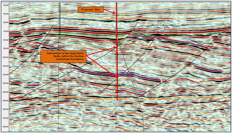
Figure 1: Interpreted Seismic Data with Large Listric Faulting in the Overburden
Drilling problems associated with faults may vary from minor erratic torque up to severe overpull and stuck bottom hole assemblies. ‘Instant’ trapping of the string while drilling-ahead in faulted formations, where the stuck point is at the bit, is characteristic of local fault shearing caused by ECD while drilling. Mobilised fault rubble can clog the string or wedge itself in the bottom-hole assembly (BHA) increasing the risk of packing off. In general, the problems are dependent upon the space between the walls of the fault and the extent of the associated rubble zone. In addition, lost circulation is often encountered where the faults have sufficient connectivity. Losses can vary from minor (a few barrels an hour) to total lost circulation at any time while circulating.
The most common reasons that drilling problems associated with drilling faults and fractures occur are:
Change in lithology: due to fault displacement, or to the presence of atypical minerals (some reactive) often found in gouge material, such as montmorillonite;
Rubble or breccia zones are the result of the crushing of wall rocks during fault slippage or from fracturing of the rock. The thickness of the rubble zone (centimetres to hundreds of metres) is a direct result of the geometry and amount of displacement (throw) along the fault. A greater throw will typically result in larger areas of damage (illustrated in figures 2 and 3, taken from Childs et al, 2009 and Torabi and Berg 2011, respectively). Particle size of the rubble material can range from sub-micron to tens of centimetres; Pieces of rubble up to 300mm in length have been retrieved from BHA components after drilling through a fault rubble zone;
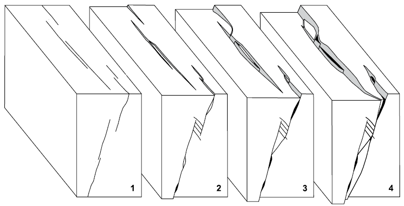
Figure 2: Fault Evolution with Increasing Displacement (Childs et al. 2009)
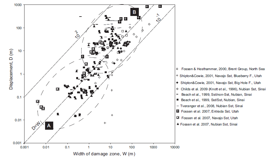
Figure 3: Fault Displacement and Width of Damage Zone for Siliclastic Rocks (Torabi & Berg 2011)
Fault or fracture connectivity can lead to downhole mud losses. The scale of the loss rate will be proportional to the connectivity of the system;
Free surface intersections from multiple fracture sets that allow loose rock to move or slide into the wellbore. This process can be made significantly worse if local wellbore failure (‘breakout’ or drilling induced fracturing) forms additional free surfaces to release rock from the wellbore wall;
Shearing/slippage along feature surfaces (i.e. faults, fractures, bedding etc.), free to move if they are pressurized (Figure 4).

Figure 4: Shear Displacement Along Wellbore Axis
Although large scale faults and fracture zones can often be anticipated there will be occasions when smaller, sub-seismic scale faults or fractures will only be recognised while drilling or inferred from variations in drilling parameters: These can include:
Minor erratic torque
Unexpected change in formation or logging response i.e. gamma ray, resistivity, density or sonic fluctuations (Figure 5);
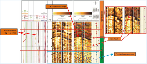
Figure 5: Fluctuations in Logging Response and Changes in Lithology on Image Log
Hole problems such as tight hole, overpull and stuck pipe;
The presence of cavings, despite using a static mud weight sufficient to maintain wellbore stability. These cavings are best described as ‘rubbly’ and do not exhibit the ‘arrow-head’ type of cavings usually prevalent in the case of classical wellbore instability (Figure 6).
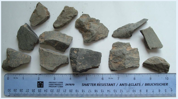
Figure 6: Typical Rubble Material Returned from a Faulted Zone
Planning to drill faulted formations requires time and care; there are no ‘instant’ fixes and no automatic processing techniques to predict problems per se. To help drilling faults successfully GeoScience has developed a threefold approach that involves detailed pre-planning to define the problems, followed by the use of specific drilling practices to mitigate the consequences together with a plan for gathering and collating data while drilling the subject well to ensure that the learnings are carried forward.
See our Oilfield Geomechanics services here.
References:
Childs, C et al, 2009. A geometric model of fault zones and fault rock thickness variation. Journal of Structural Geology 31, pp.117-127
Schultz, R.A and Fossen H, 2008. Terminology for structural discontinuities. AAPG Bulletin, v. 92, no. 7 (July 2008), pp. 853–867
Torabi, A and Berg, S.S., 2011. Scaling of fault attributes: A review. Marine and Petroleum Geology 28, pp1444-1460
Comments